A conversation that happens on site more often than it should
"What's the isolation on this coupler?"
"22dB."
"And directivity?"
"Not listed. It only says isolation."
"So can we use this part or not?"
The conversation stalls here. 22dB isolation doesn't sound bad. But without directivity, you don't know whether that 22dB comes from "the forward coupled port and the reverse isolation port are well separated," or from "the coupling is very weak, so the isolation number looks good but the directivity is actually poor."
The return loss and VSWR relationship is similar. Someone asks you, "VSWR is 1.25 — what's the return loss?" You need to immediately pull 19.1dB out of your head. If you can't, it means these four parameters have always been memorized separately, never connected.
They are not four independent specs. They are two pairs, and each pair describes two sides of the same physical fact.
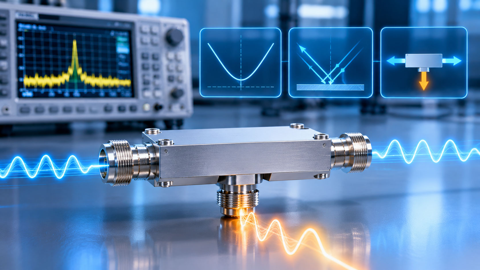
Return loss and VSWR: two translations of the same reflection coefficient
Any impedance mismatch reflects a portion of the incident power. The amount of reflection is quantified by the reflection coefficient Γ:
Γ = (VSWR − 1) / (VSWR + 1)
Once you have Γ, return loss and VSWR are both "translations" of it:
Return Loss = −20 log₁₀|Γ| (dB)
VSWR = (1 + |Γ|) / (1 − |Γ|)
One Γ value corresponds to one return loss value and one VSWR value. They are three expressions of the same set of physical facts.
What you actually need to remember in engineering is a set of anchor points:
|
VSWR
|
Return Loss (dB)
|
Reflected Power
|
Engineering Intuition
|
|
1.10
|
26.4
|
0.23%
|
Very good, almost no concern
|
|
1.20
|
20.8
|
0.82%
|
Good, typical pass line for most passive components
|
|
1.25
|
19.1
|
1.23%
|
Acceptable, but already at the edge of "good enough"
|
|
1.50
|
14.0
|
4.00%
|
Clearly excessive, find the cause
|
|
2.00
|
9.5
|
11.1%
|
Unacceptable, reflected power becomes destructive
|
VSWR 1.25 corresponds to 19.1dB return loss and about 1.2% reflected power. That number itself isn't alarming. But reflected power doesn't disappear. It travels back along the same path, passing through every component and feeder segment, adding up, forming standing waves, and losing more energy along the way. The more stages in the cascade, the more likely that 1.2% reflection at some frequency produces an equivalent VSWR much higher than 1.25.
So when a datasheet says "VSWR ≤ 1.25," the real question is: Is this the maximum across the full band, or a "typical" value at a specific frequency? Wideband devices usually have higher VSWR at band edges than at center frequency. A VSWR number without a frequency condition has limited reference value.
Isolation and directivity: directivity is the true measure of "directional" performance
A directional coupler has four ports: input, through, coupled, and isolated. Signal enters the input, most exits through the through port, and a portion exits the coupled port — that's the design intent. But the isolated port also leaks a small amount of signal. The magnitude of this leak is the isolation:
Isolation I = 10 log₁₀(P_input / P_isolated) (dB)
The power reaching the coupled port is determined by the coupling value C:
Coupling C = 10 log₁₀(P_input / P_coupled) (dB)
Directivity D is the ratio of coupled power to isolated power:
Directivity D = 10 log₁₀(P_coupled / P_isolated) = I − C (dB)
This relationship is the most overlooked and most influential for selection decisions among the four parameters: Directivity = Isolation − Coupling. Not addition, not multiplication — subtraction.
A 10dB coupler with 22dB isolation. Directivity = 22 − 10 = 12dB.
What does 12dB directivity mean? It means the power generated at the isolated port by a reverse-entering signal is only 12dB below the power generated at the coupled port by the forward signal. A 12dB rejection ratio is far from clean in a multi-port system. A coupler with poor directivity has essentially degraded into an ordinary power splitter and no longer has the ability to "couple only the signal in the specified direction."
Conversely, a 30dB coupler with 80dB isolation. Directivity = 80 − 30 = 50dB. That's the quality "directional" should have.
So when looking at an isolation number, you must also look at coupling. High isolation does not equal good directivity. A weakly coupled device can easily make its isolation number look good, while its directivity may be quite ordinary. Products whose datasheets list only isolation and omit directivity are hiding the most critical piece of information for judgment.
The "impossible triangle" among the four parameters
VSWR, isolation, directivity, and bandwidth pull against each other physically.
Low VSWR requires precise impedance matching, and wideband matching is much harder than narrowband matching. A device with VSWR 1.05 at center frequency may become 1.5 at the band edge.
High directivity requires the coupling mechanism to have sufficient selectivity for forward versus reverse signals. This selectivity is easy to achieve in a narrow band; widen the bandwidth and directivity usually drops. Microstrip couplers "basically have no directivity" above 30dB coupling for exactly this reason — weak coupling plus wide bandwidth dilutes directional capability.
High isolation requires the isolated port to be sufficiently "insensitive" to reverse signals, but in wideband designs, the rejection at the isolated port is hard to maintain across the full band.
So the engineering reality is: a wideband device rated "low VSWR, high isolation" often does not have particularly outstanding directivity. Conversely, a narrowband cavity device with 40dB+ directivity may have only a few percent bandwidth.
Maniron's product pages describe directional couplers by listing "Low VSWR & Insertion Loss, High Isolation" together. That's an engineering-honest way to present these parameters — acknowledging that they are a group of specs that need to be stated together, rather than singling out one as a selling point.
Practical judgment when reading a datasheet
When you get a directional coupler datasheet, read it in this order:
First, check whether coupling and isolation are both given. If only one is listed, ask for directivity data. Directivity = isolation − coupling. Calculate it yourself and see what comes out.
Second, check whether VSWR or return loss is given. One is enough, but verify whether it's "max" or "typical," and whether a frequency condition is stated. VSWR 1.25 max across the full band and VSWR 1.25 typical at center frequency are two different things.
Third, check how directivity varies across the band. Directivity is not a constant. If the datasheet gives only one directivity number, ask whether it's the minimum in-band value or a typical value. Wideband devices usually show lower directivity at band edges.
Finally, cross-check the internal consistency of the four parameters. If isolation is high, coupling is low, yet calculated directivity is small, or VSWR is very low but the converted return loss doesn't match, the data itself needs further confirmation.
An overlooked engineering fact
A coupler with poor directivity amplifies measurement error in power measurement scenarios. When a directional coupler is used to measure forward and reverse power, crosstalk exists between the two directional coupled outputs. Finite directivity (typically 20–30dB) means this crosstalk cannot be fully eliminated. Under full reflection conditions, forward and reverse power measurement error can reach the 10% level. A 10% measurement error means the link judgment you make from that reading carries inherent uncertainty.
In a DAS, the more direct impact of directivity is insufficient rejection of reverse signals at the isolated port. Reverse signals leak into the coupled port and mix with the forward coupled signal. If the downstream uses this coupled port for power monitoring or signal distribution, what it gets is not a "clean" forward sample. The worse the directivity, the more contaminated the sample.
One sentence to close
Return loss and VSWR are two translations of the reflection coefficient — either one works, but you need to know how to calculate the other. Isolation and directivity are two layers of directional capability — isolation is the absolute value, directivity is the margin after subtracting coupling. Isolation without directivity is an incomplete account. Only when the four parameters are read together do the numbers on the datasheet start telling the truth.